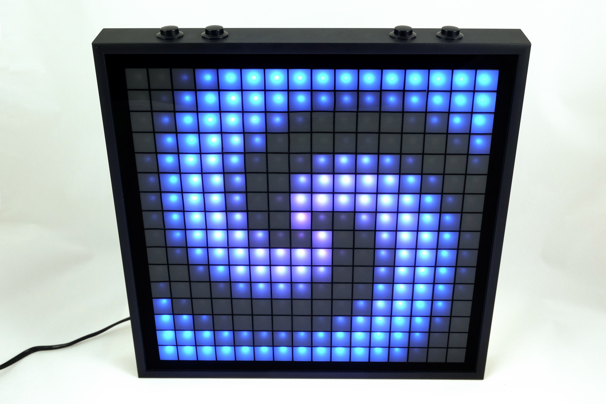
LED Matrix Materials Guide
I built an LED matrix out of 256 WS2812 LEDs. This post will describe which materials I used and which I tried with no success so you don’t have to.
Case

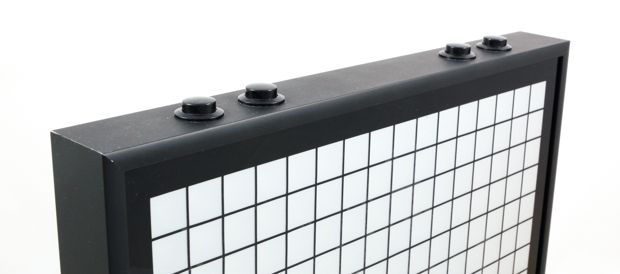
For the case, I used a custom made photo frame. The main purpose of the case is to look good, which is harder to achieve if you make it yourself. I’m using a matte black aluminium frame. Make sure it is deep enough to house all parts. My frame came with a glass plate, so I didn’t need to buy a seperate one.
I used a sheet of scrap wood as a base plate to stick the LED strips on and to mount the other components.
Dividing grid
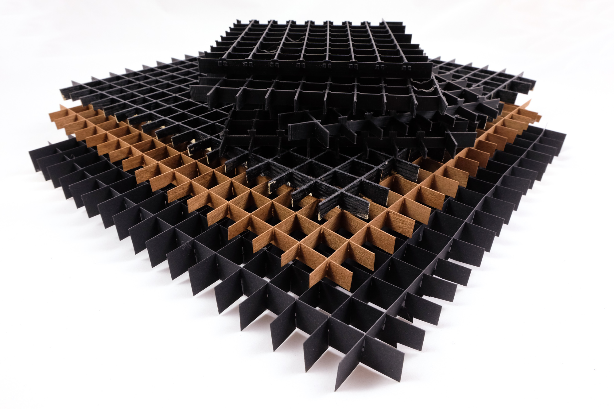
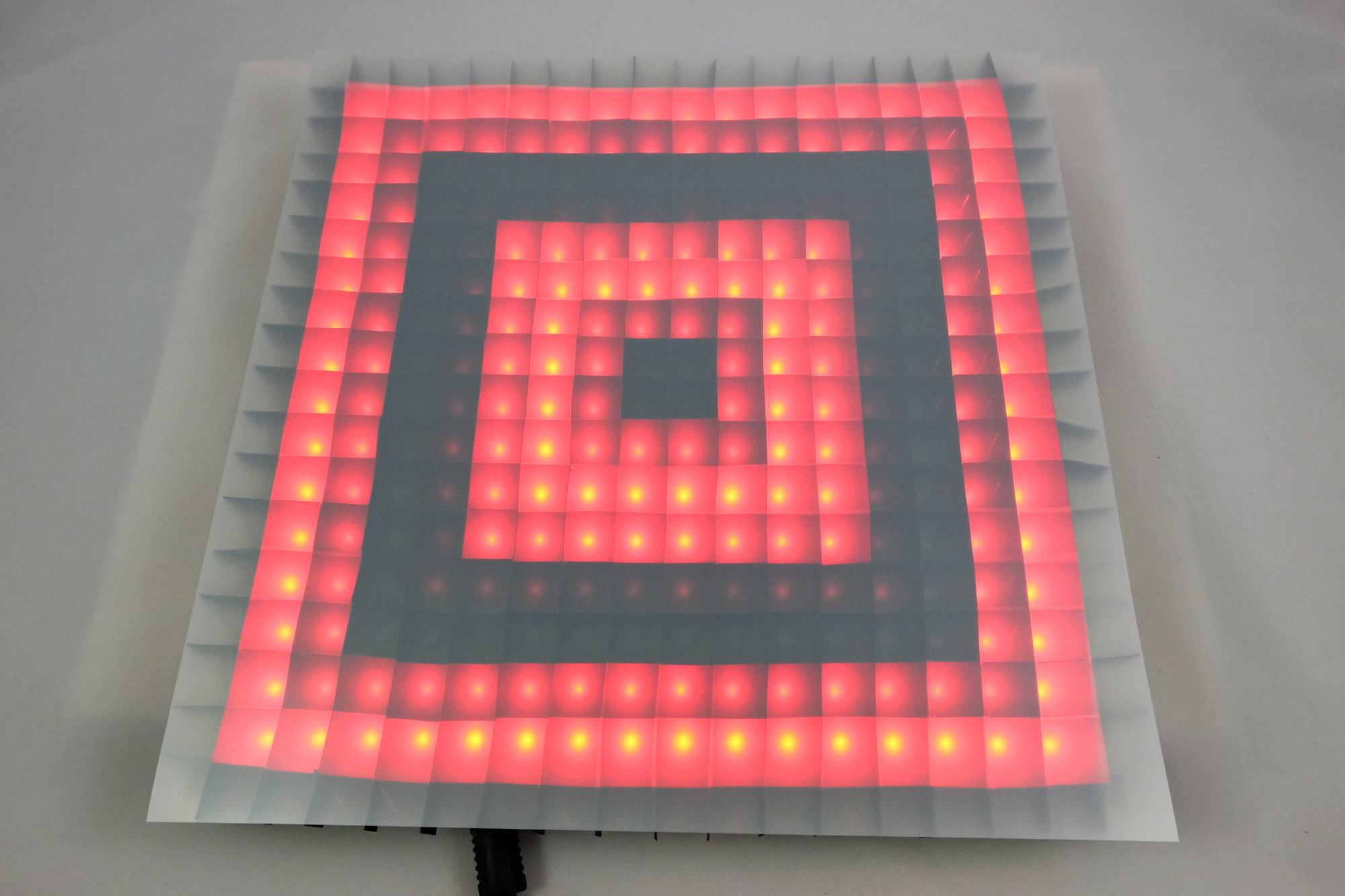
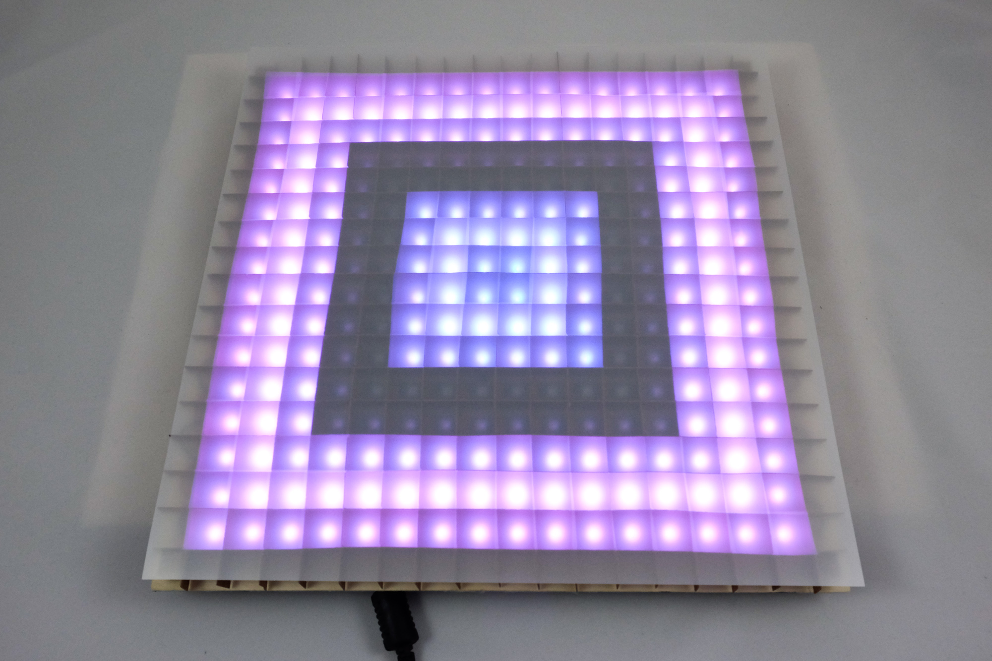
You need a dividing grid in order to prevent neighbour pixels from blending colors. Without a dividing grid, there will be no sharp edges between two pixels, but a gradient, making the resulting image look blurry.
My first try was making a grid of interlocked cardboard strips. The resulting walls bent, creating squiggly pixels.
Next, I ordered wood strips, cut notches in them and made another interlocking grid. This resulted in the same bending as the cardboard approach. Even though the wood strips bend less, small inaccuracies with the positioning of the notchces lead to tension and bend the pixels.
To get rid of the inaccuracies of manual measuring, I tried a laser cutter. My first approach was to cut the entire grid out of multiple layers of wood. The walls were too thin and the laser destroyed them. Since I only had access to the laser cutter for a limited time, I didn’t explore it exhaustively. You might get better results with the interlocking approach or with a different material.

Finally, I got a 3D printer and printed a grid. This is the one I ended up keeping for my matrix. I had to split it into four parts to fit in the printer’s build volume. If your grid model has bridges for the LED strips, you might try to print the grid with the viewer facing side pointing up in the printer. However, the unwanted flatfood effect will be visible in the LED matrix if you print your grid like this. Instead, print it so that the viewer facing layer is printed last.
Diffuser
In order to light up the entire pixel, not just a small dot in your field of view, you need something to diffuse the light.
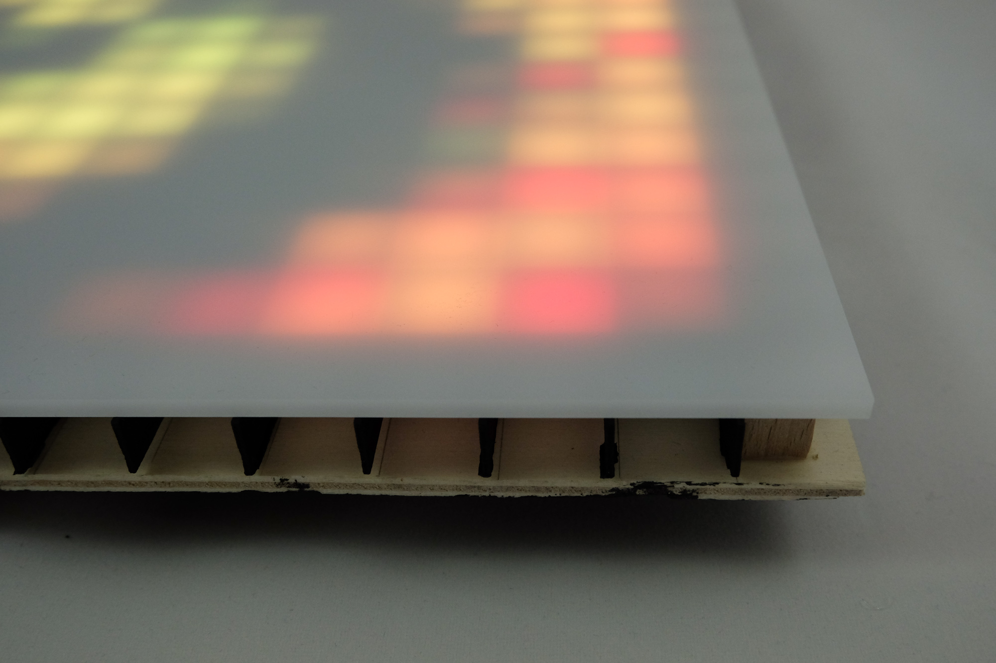
I found a sheet of diffused acrylic glass. This is not suitable for using in an LED matrix. The thicker the diffuser is, the more it blurs the image, in addition to diffusing it.
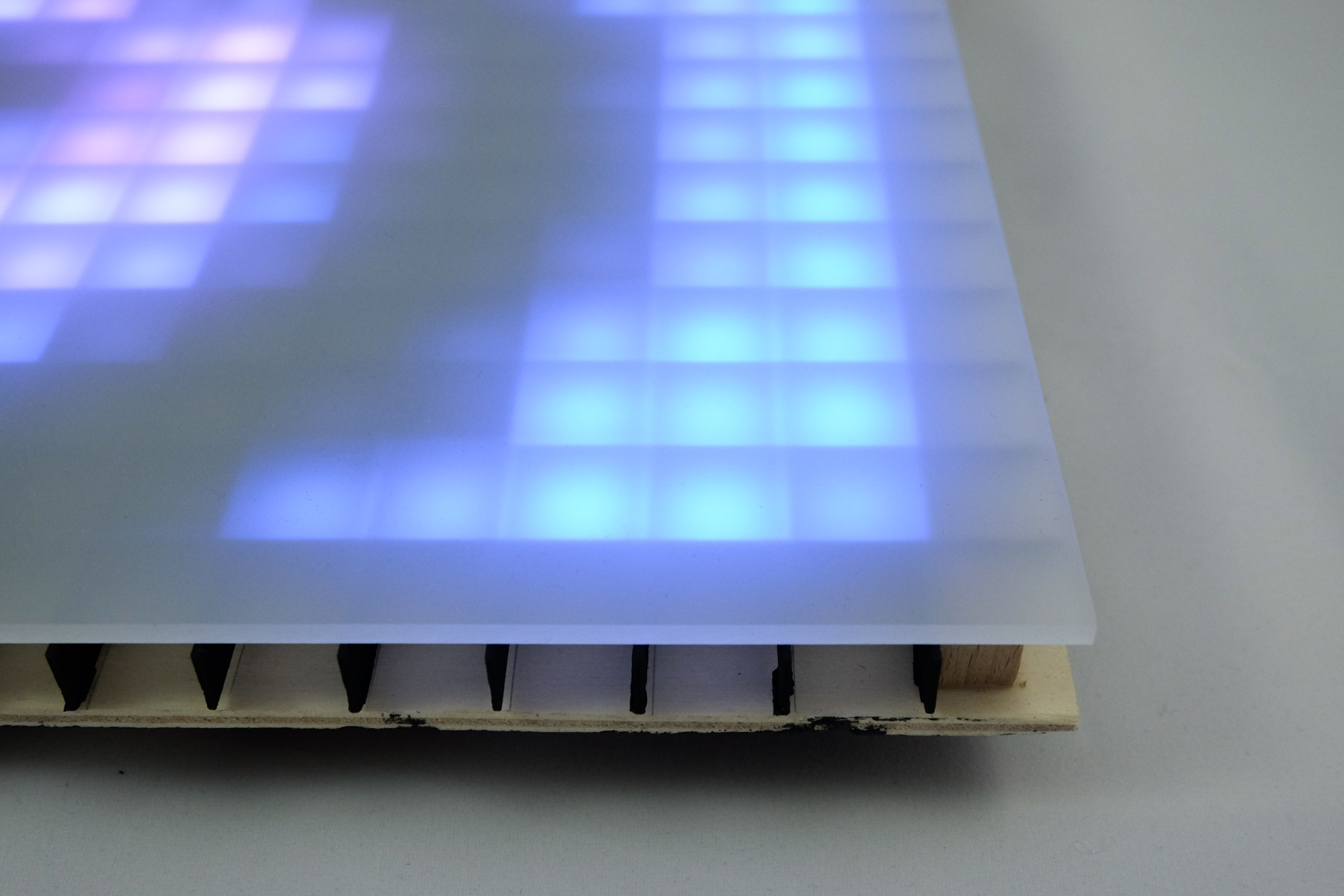
This is a thinner sheet which creates a slightly sharper image. However, for a good image, the diffuser needs to be as thin as possible.
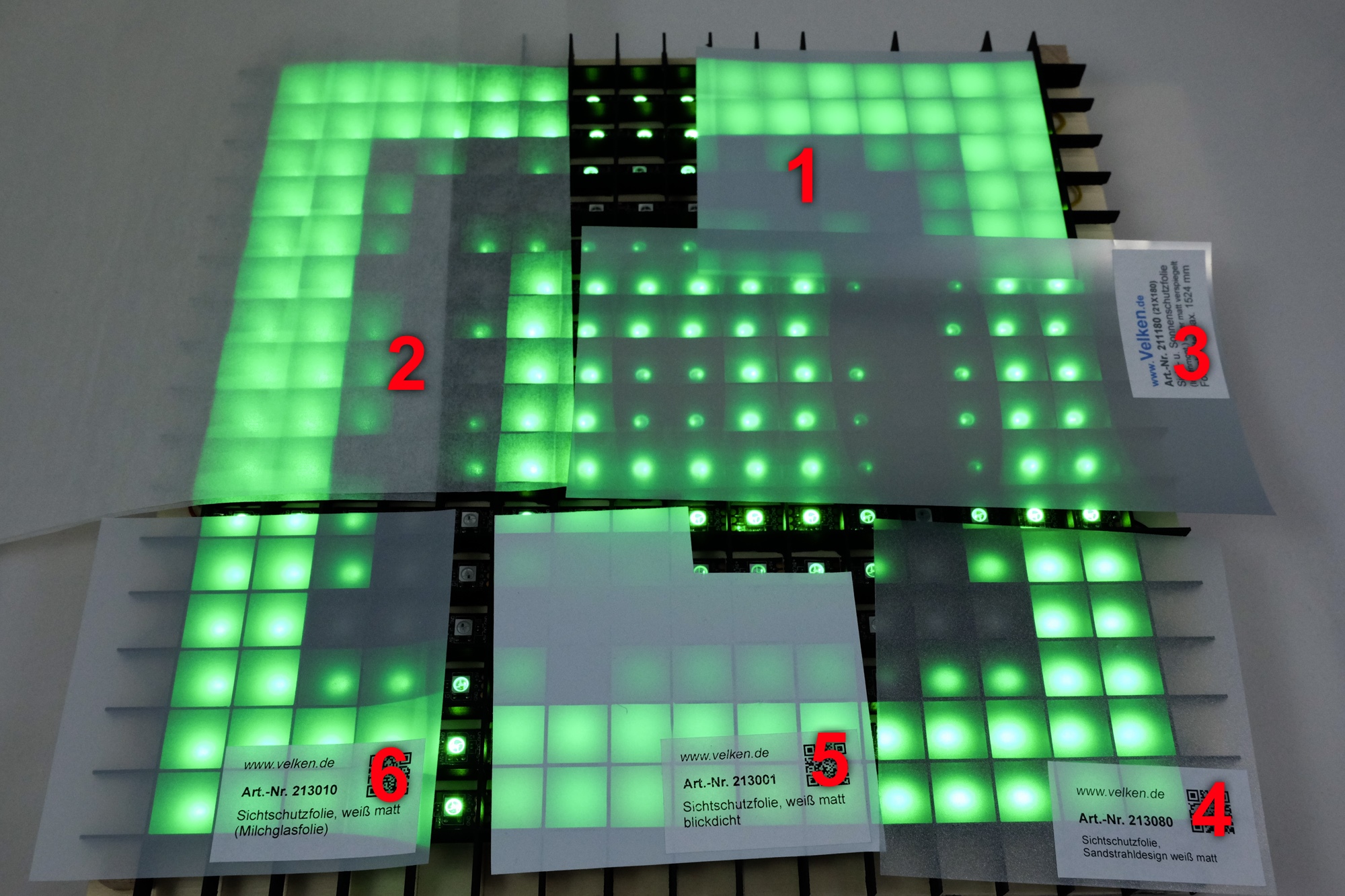
Looking for something thinner, I ordered diffusing 0.5mm thick plastic sheet from a crafting supplier (1). This still creates a bit of blur.
Next, I tried paper (2). I used vellum / transparent paper, which is sold for crafting. While still a bit too thick, and thus making the image a tiny bit blurry, the main problem was that the paper got rippled after a while. This adds an unwanted texture to the LED screen.
Finally, the solution I sticked with is a plastic foil. These are made to be put on windows for privacy. I found a website that sells these foils and offers free samples, so I got a selection of samples. Sample 3 and 4 don’t diffuse the light enough, you can make out the shape of the LED. Finally, I got sample 5 and 6 in full size. I found the non adhesive foil easier to handle. It stays in place well without being glued to the glass plate.
Electronics
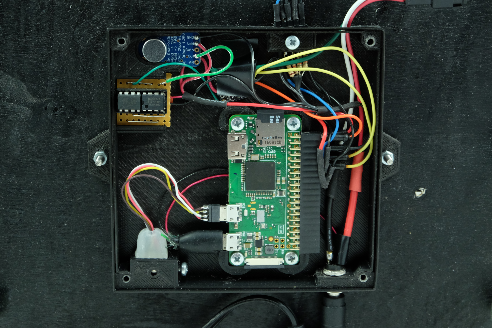
Depending on the software you intend to run on your LED matrix, I recommend using a Raspberry Pi or, for simpler projects, an Arduino. If your board operates at 3.3V, you might want to use a level shifter that converts the 3.3V signal to the 5V signal the WS2812 strip needs. However, if you feel adventurous, you can skip the level shifter and hope that the WS2812 picks up the 3.3V as a logical 1, which it will probably do.
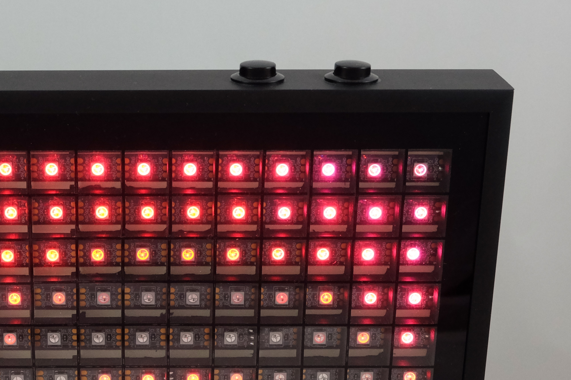
In addition, my setup has four buttons and a microphone, these are optional depending on your intended use of the LED matrix.
Adafruit has a good tutorial for setting up the LED strip and the software for it on a Raspberry Pi. You should make sure to get the strandtest.py example running before sticking the LED strips.
LEDs
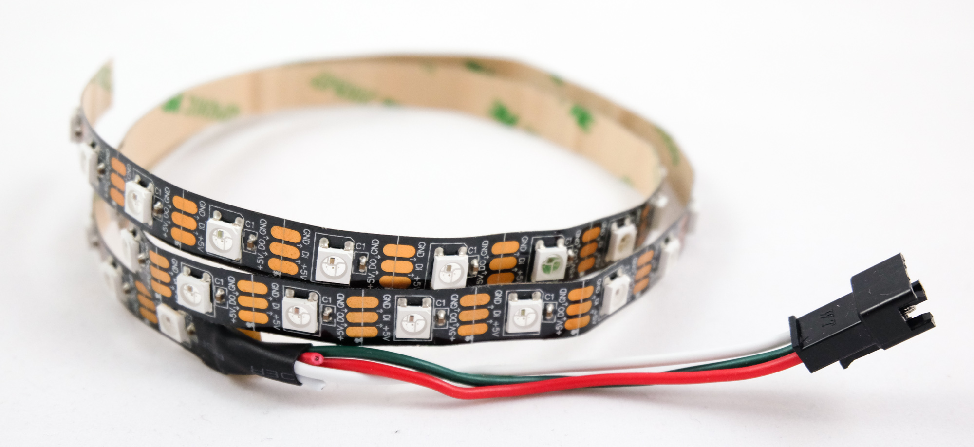
I’m using WS2812 LED strips. As long as the model is correct, just go for the cheapest offer. Check the estimated shipping time when ordering from China.
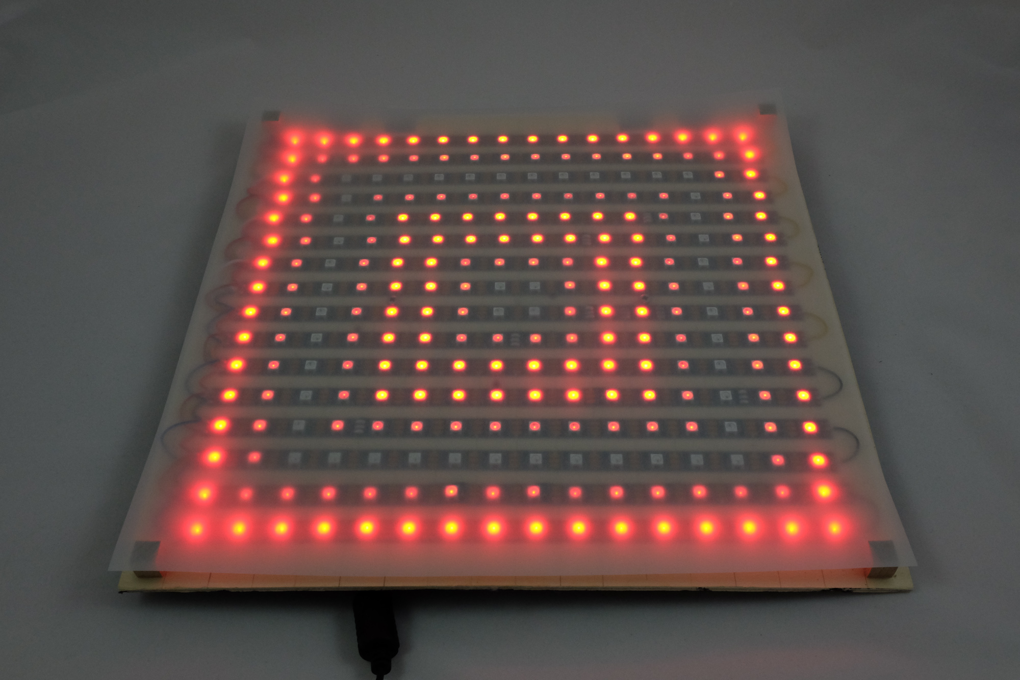
LED layout
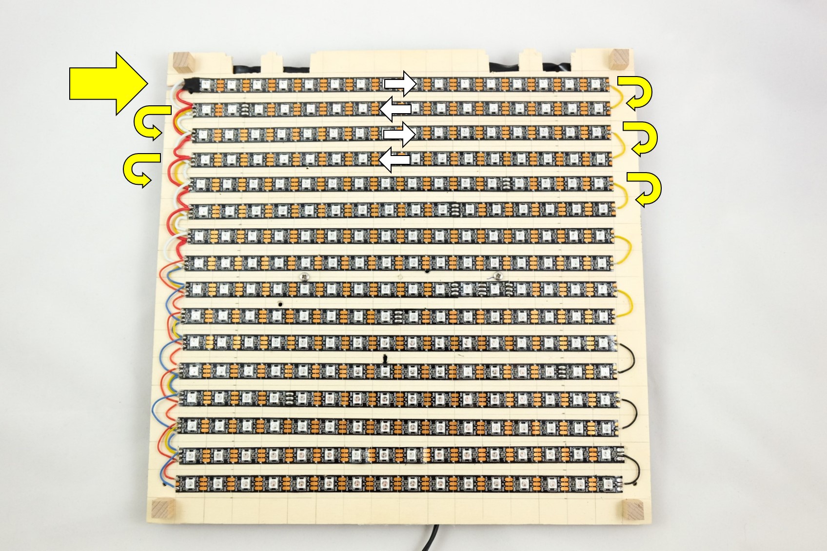
The LEDs are supplied as a single strip and will appear as such to the computer. The LED strip will be cut after every line and then placed with alternating orientation for each line of the grid. Since cutting and resoldering every pixel is tedious, you should consider the spacing of the LEDs when selecting the LED strip and chosing the spacing for your grid. I used a strip with 60 LEDs per meter. The 16 pixels plus a margin of one pixel on each end results in a 30cm x 30cm base plate. This way, I don’t need to cut after every LED, but only once per row.
Note that the LEDs are not centered between the cutting lines. You need to make sure that the LEDs themselves line up, not the cutting lines. I realized this too late.
Power supply
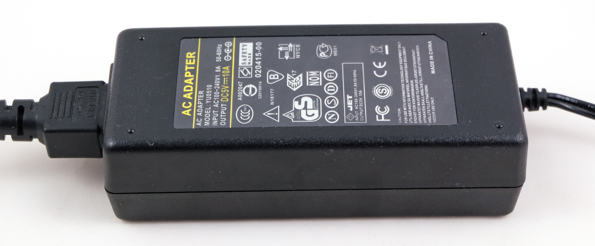
Each subpixel LED draws 20mA at full brightness. That’s 60mA per pixel or 15.3A for 256 pixels.
Going by that math, you’ll need a power supply that can supply at least 15A. However, this only really applies if you want to have your entire LED matrix on bright white for long amounts of time. In practice, a lower rated power supply will do the job. Adafruit proposes that as a rule of thumb, you can get away with 1/3 of the maximum theoretical power draw. This would be 5A in the case of 256 pixels. I’m using a 10A power supply for my project and I didn’t have any issues.
However, operating a power supply beyond specification can be a fire hazard.
Also note that running 256 LEDs at their brightest level is really bright. Unless you need a floodlight, you might want to limit the brightness anyway.
Additional hardware
Cosmetic grid
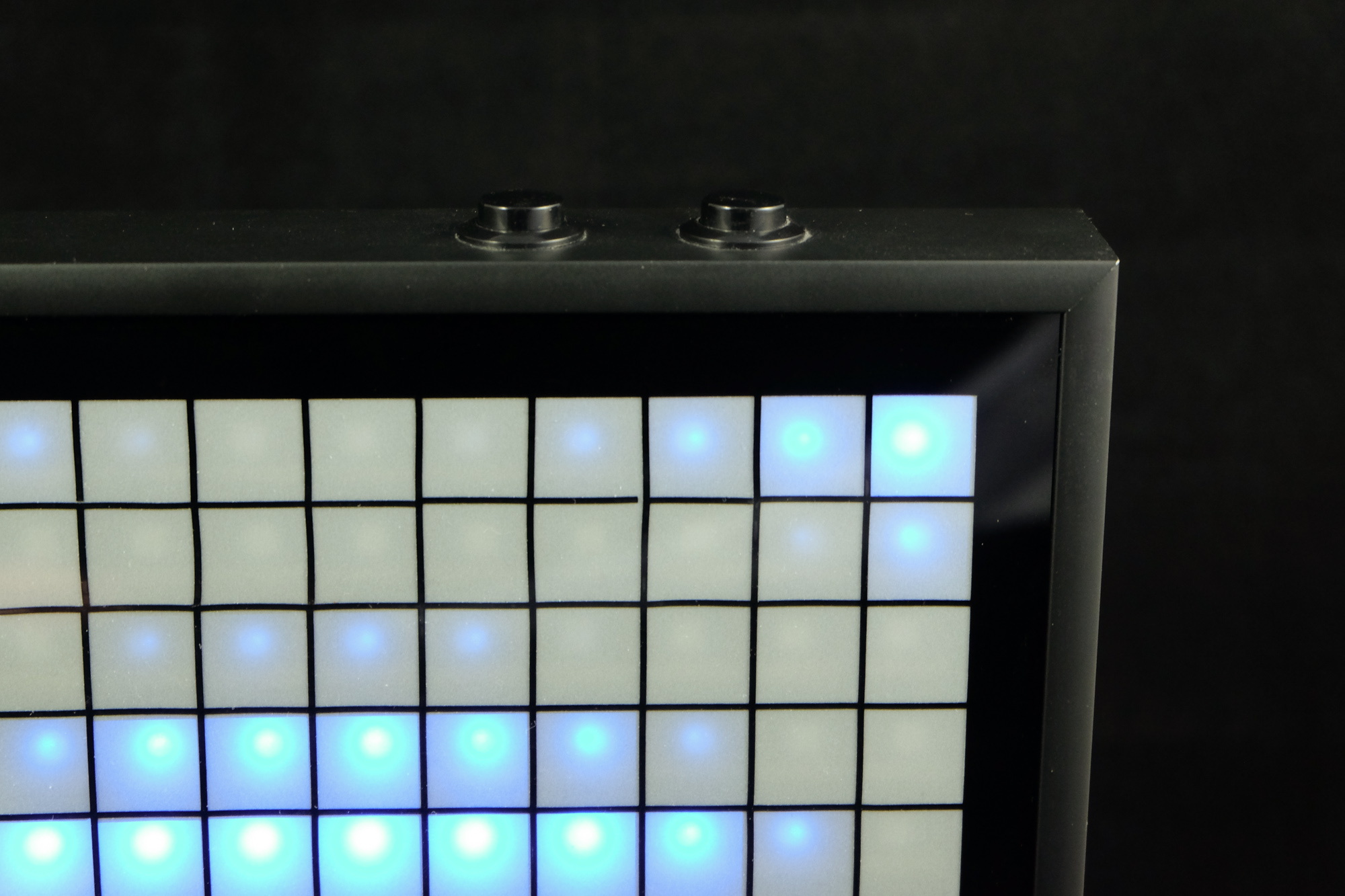
This is a thin grid made out of black adhesive foil with a cutting plotter. It is applied to the glass sheet and its purpose is to give the pixels a visual seperation, creating a sharper looking image. This is optional and I’m not entirely sure if I like the matrix better with or without it. It looks bad at places where the dividing walls behind the diffuser don’t line up with the cosmetic grid. When turned off, the grid does make it look more interesting.
Electronics case

I 3D printed a case for the electronics. This is also optional, since the matrix works perfectly well without it, but it looks cool. It also contains an USB port for the Raspberry Pi Zero W I use, so I can connect a gamepad.