Computer Vision and Robotics Demo with Raspberry Pi
This spring, I spent some time at SAP’s commercial hackerspace. I wanted to explore how computer vision can be used with embedded devices and robotics. I built a demo that can detect QR codes and similar symbols and point a laser at them. Possible applications of this are putting QR codes on objects to help the robot locate them and grab or manipulate objects. Another possible use case is local navigation. A robot could infer its own location and orientation in space by detecting QR codes with known locations.
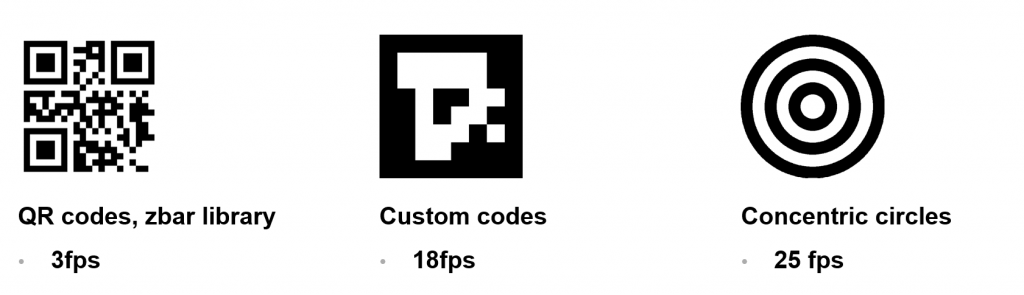
As a prototyping platform, I used a Raspberry Pi board with the Picam camera module. For QR codes, there is a library available to detect them, called zbar. The problem with zbar is that its performance is not good enough to use in robotics. On a Raspberry Pi 2B, it can scan the camera image about three times per second, which is too slow.
Therefore, I explored alternatives to QR codes. I created a new type of symbol that is simpler than a QR code and can be detected faster. The symbol detection was done using Python and the OpenCV library. OpenCV provides tools for computer vision, such as colorspace conversion or contour detection algorithms. These codes can be detected at about 20fps on the Raspberry Pi.
Due to the interpretation layer of Python, it’s not perfect for projects with critical performance. To increase performance even more, the code could be rewritten in C++, which I decided not to do for this prototype. However the performance was improved by operating on large arrays using Numpy rather than standard Python.
For even faster recognition, I designed symbols that just consist of concentric circles. These can be detected faster, but they don’t carry any data. The robot can’t tell them apart.

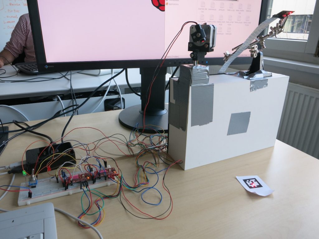
Now that the Pi knows where the symbols are, a laser is pointed at them. The setup can move a red laser on two axes, using two stepper motors. The motors are connected with 3D-printed parts and driven by two Sparkfun EasyDriver boards that provide the correct voltage and current for the motors. The Raspberry Pi uses two GPIO pins for each motor to set the direction and trigger a step.

Together with a stand for the camera, the Raspberry Pi can see symbols on the table and move the laser dot around on the table. The camera is also used to detect where the laser is pointing. Another Python script takes the symbol position on the screen and computes the corresponding motor positions.
As another way of demonstrating the laser movement and symbol detection, I wrote a version of the game Pong that is played without a screen, on the table. The laser dot is the ball and the paddles are symbols that are moved around on the table.
Finally, here is an album that shows the steps that are used by the program to analyze an image:
[](//imgur.com/yO13U)